Why bother with veterinary dental radiographs?
Veterinary dentistry is currently undergoing tremendous modernization. The days of having a technician clean tartar visible above the gum line, and “pull the loose teeth” are gone. Practice standards dictate a higher level of oral care for our patients, and dental radiology is a vital part of those standards. In fact, it is not possible to provide good quality dental care without utilizing radiographs. Most dental pathology lies underneath the gingival margin, and cannot be visualized. Without radiographs, you will miss most of the oral problems present in your patients, possibly leaving them in discomfort for years. Additionally, failure to utilize dental radiology will result in tens of thousands of dollars of missed revenue, from both the radiographs and the resulting treatment provided. The patient, the owner, and the practice all benefit from providing a higher level of dental care.
Indications
There are a number reasons to take dental radiographs. Anything out of the normal warrants a radiograph to make sure you are not missing a problem.
| Common Indications for Dental Radiograph | |
| Missing Teeth | Epistaxis |
| Fractured teeth | Evaluation of prior treatment |
| Evaluating vitality of teeth | Evaluathion of disease progression |
| Resorptive Lesions | Pre- and Post-extraction |
| Pockets over 3mm in dogs | Client education |
| Pockets over 2mm in cats | Non-dental uses:Small patient extremities BirdsExotics/ pocket petsNasal radiographs Phalanges |
| Oral enlargements/masses | |
| Draining tracts on the gums, maxilla or mandible | |
| Painful or sensitive teeth | |
| Painful or sensitive teeth | |
| Nasal discharge | |
Equipment
The equipment required to take good dental films includes intra-oral film, a method of developing the film, and a source of X-rays. A very minimal investment is required initially if you want to “get your feet wet” before diving into dental radiology. Even the $3000 investment required to be completely equipped will pay for itself in a few months in a small animal practice. The author’s most recent general small animal practice generated 17% of gross revenues from dentistry and dental related services such as pre-surgical blood screening, anesthesia, fluids, suture, and medications. Very little of this revenue was from “advanced” dental cases.
A. Dental film
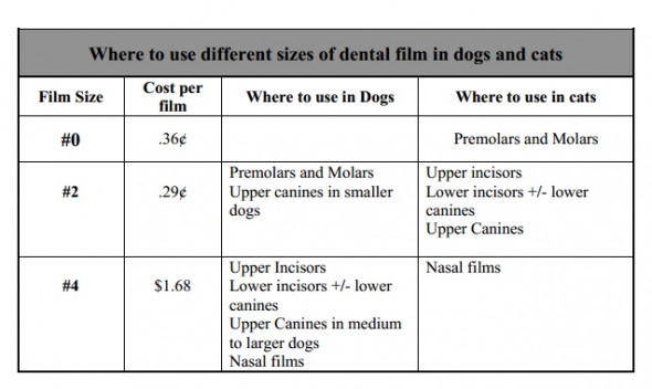
Dental film comes individually packaged in a waterproof packet, and is non-screen film. As such, the detail is much better than using traditional X-ray cassettes and film. Dental film is really the only thing you must have to take good quality dental radiographs. Three sizes of film, #0 (periapical), #2 (periapical), and #4 (occlusal), will allow you to take all dental views in dogs and cats. The three common speeds available are D, E, and F. The “D” speed film is the most forgiving of developing or exposure time errors, and provides the best detail. The “E” and “F” speeds decrease exposure times by approximately 30% and 60% respectively, but are less forgiving and have slightly lower detail. The author uses “D” speed film. The common uses for the different sizes are summarized below.
B. Developing films
For those wanting to make the minimum investment, films can be developed in your present darkroom, using coffee cups filled with the rapid developing chemistry used in automatic film processors. (Note: the use of any chemistry other than specific rapid dental film chemistry will result in decreased film quality.) You can use hemostats to grasp the corner of the film and place it in the developer. Develop the film until an image is visible when held up to the safe light. Then rinse the film briefly in a water bath, and place the film in the fixer for one minute until cleared. The film can be read at this time, but should be placed back in the fixer for an addition 3-5 minutes to ensure complete fixation. When completely fixed, the film will lose all traces of a greenish color. The film should then be rinsed in running water and placed in a clean water bath for 10-15 minutes. This is followed by a final rinse to remove all traces of fixer. Be sure to remove the hemostat and rinse all film surfaces thoroughly. Traces of fixer remaining on a dental film give it a characteristic “slick” feel, so rinse under running water while gently rubbing the film between your fingers until the film does not feel slick.
Although some texts have recommended the use of distilled water to rinse films, the author has not found this to be necessary as long as all traces of fixer are removed. The film can then be leaned against a wall or object and placed on a paper towel until dry. Some people prefer to use drying racks, which are available in a variety of configurations. Although the above technique can produce quality films, the use of a chairside developer, specific dental film chemistry, and film clips made for dental films will improve the quality of your films and make your life much easier. If the process is convenient, you will find yourself taking more films… and finding more pathology to treat.
The use of a chairside developer makes developing films easy and convenient. You will save time, and be able to develop and read your films in only 1-2 minutes. The chairside developer allows you to easily judge when development time is correct, and lets you stay next to the patient while the film is developed. The units take up very little space, economize your chemical use, clean up easily, and store quickly. Do yourself a favor and get one. The developing technique is the same as described above. Dental film clips simplify film handling and drying. Dental-specific film chemistry enables rapid developing and fixing times. The chairside developer, chemistry, and film clips in the Dentalaire dental catalog are the same ones used by the author.Be sure to change the chemistry whenever the developing and fixation times seem to be slowing down. This will occur after you have developed and fixed around twenty smaller (#0 or #2) films, or ten larger (#4) films. Use of exhausted chemistry results in poor image quality.
C. Digital Radiography
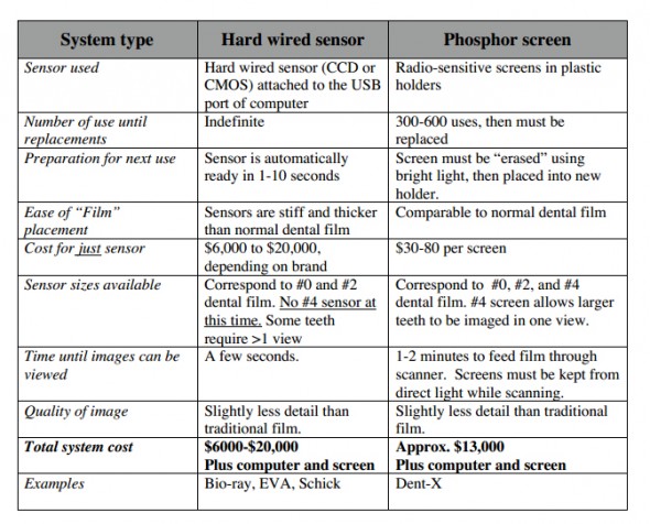
A newer development in dental radiography is the availability of digital systems. Digital systems use either a wired sensor or a phosphor screen instead of film. The wired sensor models allow an image to be viewed within seconds on a computer screen. When phosphor screens are used, the screen, which appears similar to dental film, must be fed through a scanner, and the image can be viewed in 1-2 minutes. Image quality depends a great deal on the software used to process the image. Most available software allows for the manipulation and enhancement of the image, which decreases re-takes. As digital communication becomes the standard, digital imagery will become the norm in clinical practice. All of these systems require some computer literacy. Some of the available systems can be integrated with many of the currently used practice management software programs to provide an imaging suite. The imaging suite can then be used to store and review not only digital dental films, but also ultrasound images, endoscopic studies, EKG’s, CT scans, full size radiographs, MRI’s, or any other images that are digital in origin or that can be scanned. Some savings that a digital system provides include elimination of film or chemistry costs, no chemical disposal costs, no regulatory costs of tracking chemicals and their disposal, decreased film storage costs, and decreased employee time to develop and file radiographs. Some features of the two current types of digital dental radiographic systems are presented below.
D. X-ray machines
Traditional X-ray machines can be used to produce diagnostic dental films, but positioning the patient and moving the patient to the machine’s location can be cumbersome. To use your regular X-ray machine, the film-focal distance needs to be modified, and the beam collimated appropriately. The following technique can be used as a starting point for obtaining dental films while using intraoral film with traditional X-ray machines.
- Film Focal distance 16 inches
- Time of .1 second
- MA of 100 (for a total technique of 10 MaS)
- Kv of 65-90, depending on the size of the patient (cat to large dog)
A dental X-ray machine has preset Ma and Kv, is well collimated, and is easily positioned. The only technique variable is the time of the exposure, which is easily determined. Films can be taken without moving the patient from lateral recumbency. Time will be saved due to improved convenience and a decrease in the number of re-takes required. Placing a dental X-ray machine in the area where dental procedures are performed will increase the number of dental films taken by a factor of 3-6 times. Taking more films means finding, and treating, more painful dental pathology.
There is no better equipment investment that will make you money in small animal practice than a dental X-ray machine.
E. Miscellaneous equipment and supplies
- Film storage: Several systems work well to store dental films. The films can be simply placed in a pill-type envelope which is labeled with the patient information and either placed in the medical record or in a separate dental radiograph storage area. Dental film mounts can also be used to organize films.
- Chairside illuminator: A small dental X-ray illuminator can be located next to the chairside processor. This is very convenient and will save time when reading films. A simple 2-4 power magnifying glass will usually suffice
- Automatic film processors: Small automatic film processors are available for dental films. They provide consistent film development, but add 3-4 minutes to the development time. The practice of attaching films to a large film and running it through a full sized automatic X-ray processor is not recommended.
- Magnification: a variety of magnification devices are available. They can assist in appreciating small changes frequently present on dental films. A simple 2-3 power magnifying glass will suffice in most cases.
Positioning for dental radiographs
As with regular radiographs, correct positioning is required to produce a diagnostic dental film. Correct positioning requires correct, tube angulation, tube position and film position. Any mistake made in positioning will involve one of these three parameters. With a little practice, anyone can learn proper positioning
A. Tube angulation
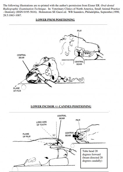
There are two basic positioning techniques used in dental radiology. The parallel technique is used in imaging the lower premolars and molars. In this technique, the plane of the tooth and film are parallel, and the beam is directed perpendicular to them both. This is the same technique used in taking a lateral radiograph of an extremity in a dog or cat. The resultant image is relatively undistorted.
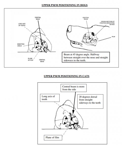
The second technique is the bisecting angle technique, and some modification of this technique is used in all other areas of the mouth. This technique is required because the anatomy of much of the oral cavity prevents the film from being placed in the same plane as the tooth. This is most obvious in the maxillary quadrants, where the film lies horizontally on the palate, while the long axis of the teeth are in a vertical plane. As a result, it is impossible for the beam to be perpendicular to both the film and the tooth. To compensate for this anatomical limitation, the beam is angulated so that it is halfway between perpendicular to the film and perpendicular to the long axis of the tooth. Although
this technique results in some image distortion, the image is clinically satisfactory.
A. Tube position
There is a tendency for beginners to center the tube head over the crown of the tooth, resulting in a radiograph with no roots visible. The roots will usually be cut off at the edge of the image, which is termed “cone cut”. In most cases, simply center the beam on the gingival margin so both the crown and root structures are present on the radiograph. If you cut your object off at the edge of the beam, move the beam over in the direction of the cone cut.
A. Film Position
Be sure to place the white side of the film packet towards the X-ray beam. Placing the film
backwards results in a poor quality film with a characteristic “waffle” pattern on the film.
If the film is placed incorrectly, the result is an image that is not centered on the film, with part of the desired target lost off the edge of the film. In all cases, you need to place the film where the image will be projected. When using the parallel technique for premolars and molars, this is easy to visualize. When the tube head is angled, the image will be projected in the same direction the tube is angled. The principle is the same as a tree’s shadow produced by the sun. The position of the shadow varies as the sun moves around the sky. The film must be placed so you catch the radiographic “shadow”. You can visualize this principle using a pencil and a penlight. Usually you will produce the best results when the film is placed as far as possible into the mouth, with only a small amount of film protruding out of the mouth around the teeth to be imaged. If you cut your object off at the edge of the film, move the film over in that direction.
Positioning for the different areas of the mouth
Five different areas of the mouth each require unique angulation of the X-ray beam. The author has “pre-bisected” the correct angles for your convenience. The dental radiology “cheat sheet” chart on the next page contains a brief summary to help you image each of these five areas. The basic positioning techniques and angulation are the same for both dogs and cats, with the exception of the maxillary premolars and molars. Cats require a slightly modified technique to avoid superimposition of the Zygomatic Arch over the dental structures. Included in this cheat sheet are some simple rules about how to detect and adjust for positioning errors.
Cranial and caudal angulation may also be employed to separate overlapping structures when imaging any area of the mouth. A common example would be utilizing cranial or caudal oblique views to separate the two front roots of the upper fourth premolar (carnassial) teeth. If you are unsure whether or not a suspected radiographic abnormality is truly associated with a tooth, simply take an oblique view and compare it to the original view. If the lesion stays in close association with the tooth, it is likely associated with the tooth and not a superimposed artifact.
| Dental Radiology “CHEAT SHEET” | |
| Area imaged | General Technique and Tips |
| Lower PM and M | Place film in vestibule between the tongue and teeth. The beam is angled perpendicular to film. This is the only “parallel technique”. |
| Lower incisors +/- Canine | Start by aiming beam on ventral midline perpendicular to the film. Then tip the tube head forward 20 degrees so the beam is angled 20 degrees caudally. If desired, using larger film will allow visualization of the lower canines on the same film. |
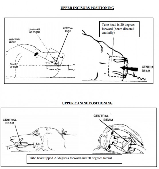
| Upper incisor | Start by aiming beam on the dorsal midline, perpendicular to the film. Then tip the tube head forward so the beam is angled 20 degrees caudally. |
| Upper canines | Start by aiming beam dorsally over the top of the canine, similar to the upper incisor view. Then tip the tube head 20 degrees forward and 20 degrees to the side. This will move the image of the root away from the premolars. The film should slightly overlap the tip of the crown forward and to the side.. Excessive film sticking out of the mouth is wasted. The forward tipping elongates the tooth, while the lateral tipping serves to move the canine tooth away from the overlapping premolars. |
| Upper PM and M | Place the film mostly over the palate. Start dorsally over the top of the target teeth. Tip the tube head 45 degrees to the side of the face. Cats require a modified technique to avoid superimposition of the Zygomatic Arch. The film is placed diagonally across the mouth from the inside of the maxillary teeth on the side opposite that to be imaged, to the inside of the mandibular teeth on the side to be imaged. Position the patient so that the target teeth are on top and the teeth line up parallel to the table top. Start the beam lateral to the maxillary premolars, and tip the tube head 20 degrees over the top of the nose. Tipping too little cuts off part of the target teeth from the edge of the film. Tipping too far accentuates the Zygomatic Arch. |
“Three Simple Rules”
The three parameters of tube angulation, tube position and film position
can be summarized as follows:
- If the image is foreshortened or elongated, adjust the tube angle. To make the roots longer, move the tube head more laterally.
- If you cut the target off at the edge of the beam (cone cut), simply move the beam over toward the area of cone cut.
- If you cut the target off at the edge of the film, move the film over toward the area you cut off
Viewing and interpreting dental films
A. Film Orientation
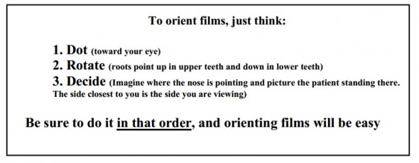
Dental films have no markers except for a raised dot (dimple) that can be felt or seen on the film. The dot can also be seen on the outside of the film packet prior to developing the film. This dot can be used to correctly orient the film for viewing, by following three simple steps.
- Place the convex (raised) side of the dot toward you. This orients the film as if you were outside the animal’s mouth looking in. Imagine your eye being in the same position that the X-ray tube was in when the film was taken. Once the dot is toward your eye, do not flip the film over.
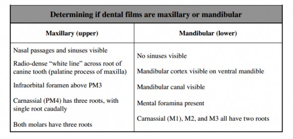
- Determine if the film is of the maxillary or mandibular quadrants. If needed, rotate the film so upper teeth (maxillary) have the roots point up, just as if you were looking at the patient’s mouth from outside the mouth. Mandibular quadrants are rotated so that the roots point down, again just as if you were outside the patient’s mouth looking in. We do not want to evaluate the patient upside down, so we rotate as needed to position the patient in a normal standing position (not upside down). Specific things to look for to help decide which quadrant you are looking at are listed below. After a little practice, it is very easy to tell maxillary and mandibular films apart.
- Determine if the film is from the right or left side. The simplest method is to identify which end of the radiograph is towards the front of the patient and which is toward the back. Imagine the patient standing in front of you with the nose in one direction and the back of the head in the other direction. Then, simply imagine the whole patient standing in front of you facing that direction. The side of the patient closest to you is the side you are viewing. Initially, you can use a skull or dental model to help you decide which side you are looking at. Very soon, it becomes second nature. Pay attention to increasing size of teeth in the premolar region, as well as unique anatomy in the carnassial teeth areas to help you out. Initially, it may be helpful to keep track of where the films were taken and to mark the films with a fine tip permanent marker (rt. upper, lt. lower, etc.) after they dry.
B. Normal structures visible on dental radiographs
You should be able to find these structures on most dental radiographs. For a more complete list of structures and examples, see the dental radiology texts in the appendix. Normal radiographs will be shown as part of the laboratory.
- Enamel
- Dentin
- Root canal system, consisting of the pulp chamber and root canal
- Periodontal Ligament Space
- Alveolar bone and Alveolar Crest
- Trabecular bone
- Cortical Bone
- Mental foramina
- Infraorbital foramen
- Mandibular Canal
- Mandibular Symphysis
- Nasal Septum
- Nasal Turbinates
- Furcation of the tooth
- Root apices (ends of the roots)
B. Radiographic signs of common dental diseases
A variety of pathologic conditions will be presented in the film reading session. Below are some of the most common radiographic abnormalities encountered.
- Periodontal diseasePeriodontal disease is radiographically characterized by loss of bony support. Early in the process the Alveolar Crestal Bone is blunted interdentally, as well as at the furcations (area between the roots of a multi-rooted tooth). The periodontal ligament space may widen as the process worsens, leading to eventual exposure of the apex of the root to infectious organisms.
- Feline Odontoclastic Resorptive Lesions (FORL) Resorptive lesions occur most commonly in cats, but can also be seen in dogs. Dental radiographs commonly show a lucent area near the gingival margin, as well as varying degrees of root destruction and bony replacement of root structures. Radiographs of these lesions serve to guide your treatment options. Some very small lesions can exhibit a tremendous amount of root destruction that is otherwise hidden.
- Endodontic DiseaseThe hallmark of endodontic disease is the presence of a periapical lucency or “halo” which indicates an area of demineralized bone. Such lesions are usually not visible until 60% of the cortical plate has been destroyed. When you see a distinct periapical lesion, it is telling you that you should have done something months or years before. Absence of periapical lesions does not mean that there is no endodontic disease. The Lamina Dura is the “white line” just outside the periodontal ligament space, and is actually the dense alveolar bone. Although the Lamina Dura is not always visible radiographically, loss of continuity of the Lamina Dura, with or without widening of the periodontal ligament space, is suggestive of endodontic disease.
Appendix
A. Materials recommended for dental radiology
- Dental X-ray machine
- Kodak D-speed dental film in sizes #0, #2 (periapical) and #4 (occlusal).
- Chairside developer (INSTA-VELOPER chairside darkroom)
- Chairside chemistry (Insta-neg and Insta-fix)
- Film Clips – 1 Dozen
- Envelopes for storage
- Small illuminator for viewing films near developing tank
B. Recommended texts for dental radiology
- An Atlas of Veterinary Dental Radiology, DH DeForge, DVM FACV, BH Colmery III, DVM, Dipl. AVDC, Iowa State University Press, Ames IA, 2000
- Atlas of Canine and Feline Dental Radiology, TW Mulligan, DVM, Dipl. AVDC, MS Aller, DVM, Dipl AVDC, CA Williams, DVM, Dipl AVDC, VLS, Trenton NJ 1998
- Oral-dental Radiographic Examination Technique. In: Clinics of North America, Small Animal Practice – Dentistry (ISSN 0195-5616). ER Eisner, Holmstrom SE Guest ed. WB Saunders, Philadelphia, September,1998; 28:5:1063-1087.

